Lashing & Stability Calculator (Heavy Haulage)
Application of standard principles NF EN 12195-1:2010
1. Cargo & Vehicle Parameters
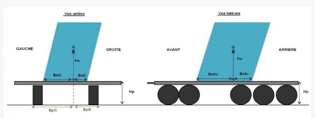
CARGO support geometry (Bs):
VEHICLE support geometry (Bp):
2. Lashing Configuration
Technical detail of added lashing elements
| Position | Component | FWD (daN) | AFT (daN) | LEFT (daN) | RIGHT (daN) | Action |
|---|
3. Sliding Stability Balance (Values in daN)
Comparison Total restraint force (Friction + Lashing) vs Inertia (Weight x G Coefficient)
Front (0.8 g)--
Rear (0.5 g)--
Left (0.5 g)--
Right (0.5 g)--
4. Cargo tipping stability (Alone, without lashing)
Safety criteria: Geometric ratio (Base / CG Height) must be greater than the acceleration coefficient (g).
Front (0.8 g)--
Rear (0.5 g)--
Left (0.5 g)--
Right (0.5 g)--
5. Road combo stability (Vehicle + Cargo) at tipping
Safety assumption: Combo CG positioned at total height H = Deck Height + Cargo CG Height.
Left (0.7 g)--
Right (0.7 g)--
DISCLAIMER AND LIMITATION OF LIABILITY
Indicative use: This report is automatically generated for preliminary technical information purposes. It does not constitute an execution expertise or a specialized engineering office opinion. Results are based on data entered by the user and the principles of the EN 12195-1 standard.
Exclusion of liability: The software author, site publisher, and developers disclaim all liability for any direct or indirect damage (material, physical, or financial) resulting from the use of these results. The end user is solely responsible for the use of the data produced by this tool and must have their loading plans validated by a safety advisor or a competent expert before any transport.
Methodological Note & Frameworks
This document details the physical principles and calculation algorithms used to evaluate cargo stability.
1. Normative Framework
The tool is based on the NF EN 12195-1 (2010) standard. It calculates the restraint forces required to compensate for accelerations of 0.8g forward and 0.5g backward and sideways.
2. Sliding Equation
The balance compares the inertia force to the restraint capacity (Friction + Lashing):
Force Retenue = (Poids × µd) + Σ (Forces Arrimage Direct) + Σ (Friction Arrimage de Force)
3. Tipping Stability
The risk of tipping is evaluated according to the geometric criteria of the standard:
- Cargo alone: Stable if (Support base / CG Height) > acceleration (g).
- Road combo: Lateral analysis based on a reference acceleration of 0.7g (heavy haulage standard).
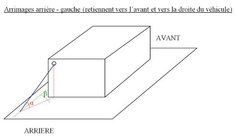
4. Breakdown of Lashing Forces
For each element, the tool breaks down the tension (LC) according to the Alpha (vertical) and Beta (horizontal) angles:
- Longitudinal Restraint = LC × cos(α) × cos(β) + (µd × LC × sin(α))
- Transversal Restraint = LC × cos(α) × sin(β) + (µd × LC × sin(α))
- Transversal Restraint = LC × cos(α) × sin(β) + (µd × LC × sin(α))
Note: A transmission factor k=0.9 is applied in accordance with the standard to account for tension losses.